Tube Operation, Cathode-bias vs Fixed-bias, and Class A vs Class A/B

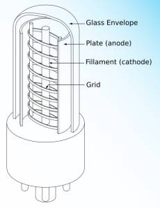
Triode Tube Diagram

Triode Tube Diagram

There is a lot of misunderstanding among guitarists regarding exactly how Class A, Class A/B, cathode-bias and fixed-bias amps operate and differ from one another. The following post addresses this topic thoroughly. First it is important to clarify the fundamentals of how a guitar tube (valve) actually operates.


 How a Vacuum Tube Actually Operates

The crucial functioning components of a tube (see above illustration) are the control grid, the cathode and the plate. These three components are the functioning parts of a triode tube. Note that there are other common guitar amplifier tubes called tetrodes and pentodes as well, and these tube types feature extra grid components called a screen grid and suppressor grid respectively. For the sake of addressing the most important fundamentals of tube operation, we’ll keep the scope of the following information to triode tubes.

Within a triode tube the plate has a positive charge, which attracts electrons. The grid is the audio input to the tube and controls the flow of electrons. There is a high voltage on the plate of the tube and a heated cathode that emits negative electrons (called thermionic emission—a main component of the “magic” of tubes). Because of thermionic emission, heat from the filament causes free electrons to boil off of an oxide coating on the cathode. Voltage on the plate attracts the electrons from the cathode, and the moving electrons produce a current flow.

Amplification happens when a signal is applied to the grid and flows through to the plate. Because the signal voltage is relatively low and the plate current is relatively high, small changes produced by the audio signal at the grid become much larger at the plate and amplify. That flow needs to be “controlled” somehow, which is accomplished via biasing. A tube cannot tell the difference between having the grid negative (fixed-bias) relative to the cathode or the cathode positive (cathode-bias) relative to the grid. A tube has no idea what class it’s operating in—a change in input voltage yields a change in plate current regardless of class. So output can swing the same amount in either direction before clipping. The limits of the power supply, and the idle point of the triode in a tube amp, determine whether “cutoff” or “clipping” will occur and the level of symmetry or asymmetry of the wave shape.

It’s important to note where in your arsenal of equipment you can find this small fluctuating AC voltage that controls this plate current—at the other end of the guitar cord via the guitar pickups. So what happens when you take this plate current and plug it into a speaker? The large current flowing through the plate fluctuates with the same frequency as the small guitar pickup voltage, and the tones we love come through. Hence, the tube amplifies the guitar signal. It makes the small AC signal coming from your guitar pickups big enough to move a speaker cone.

Cathode-Bias
In Class A cathode-bias current flowing through the tube flows through the cathode resistor, developing a slightly positive voltage at the cathode, so the cathode is positive relative to the grid. Current is flowing at all times. Because there is no current flowing through the grid and resistors, the grid is grounded at zero volts. In addition, the positive voltage at the plate is lessened by the slightly positive voltage at the cathode, as the tubes only see the difference between the cathode voltage and plate voltage. Positive cathode-bias is developed by drawing current through the cathode resistor.

Let’s assume that a tube needs the grid to be at -2 volts. That means that the cathode is at 0 volts and the grid is at -2 volts. Now suppose we add 2 volts to both values. The grid voltage becomes 0 volts and the cathode voltage becomes +2 volts. The grid is still -2 volts away from the cathode, which is required.

By biasing some DC voltage has been established on the grid (negative voltage for fixed-bias or 0V DC for cathode-bias). When the AC signal is added from guitar pickups, it can be thought of as an AC signal with a DC offset. In the cathode-biased model, the AC is oscillating around ground (going positive and negative). In the fixed-bias model, the AC signal is oscillating around the negative bias voltage (going less negative and more negative). That said, it should be clear that you’ve always got some DC offset to the AC signal (even if it is zero), and applying AC signal is the equivalent of varying the DC up and down—turning the tube “more on” and “more off” as it oscillates.

As current starts to flow, a voltage drop is created across the cathode resistor, which raises the DC voltage of the cathode. Because the grid is at 0 volts (DC), the grid is now negative with respect to the cathode and that controls the flow. If put in a tube that wants to run “hot,” the extra current simply increases the voltage drop across the cathode resistor and that tends to self-correct. In a cathode-biased amp, tubes with a fairly wide range of parameters will bias very similarly, determined largely by the value of the cathode resistor, not the tubes—this is why the circuit is “self-adjusting.” You still need matched sets in an amp with shared cathode resistor (most of them are), or the tubes will idle at different currents.

As the input signal swings positive, the grid becomes less negative. This allows more electrons to pass through to the plate, which means an increase in plate current. The voltage drop across the plate resistor becomes greater and because the B+ end of the resistor is at a fixed voltage, the plate end becomes less positive. So as the grid voltage goes up, the plate voltage goes down. This is the nature of this type of amplifier circuit. When the input signal swings negative, the more negative grid reduces the number of electrons passing through and the plate current is reduced. This causes the drop across the plate resistor to decrease and the plate voltage gets closer to the B+ voltage, or higher. Neither the grid voltage nor the plate voltage gets all the way to zero. If it did, the amount of distortion would be very high.

Fixed-Bias
In Class AB fixed-bias the cathode is grounded, and a constant negative voltage is applied to the grid. The tubes draw current directly from a grounded cathode and the voltage remains stable. Fixed-bias power tubes do not have a cathode resistor—the only way to make the grid more negative than the grounded cathode is to apply negative voltage to the grid. So, the power supply has circuitry that generates a negative voltage. As you make that grid bias voltage more negative, you “choke” the idle current flow more and more, and as you make it less negative you allow more and more idle current to flow. A negative bias voltage on the grid repels some of the electrons and prevents them from reaching the plate, resulting in less current flow. In this way a changing negative charge on the grid modulates the plate current.

Class A vs. Class AB Conduction
A sine wave is divided into degrees just like a circle. Zero degrees is where the signal crosses the center or 0 volt line and starts to go positive. Ninety degrees is where the signal is most positive. At 180 degrees, the signal crosses the center or 0 volt line again and goes negative. The most negative point is at 270 degrees, and 360 degrees is where the signal crosses the center line again, going positive. Because audio signals are basically sine waves, a tube conducting for 360 degrees is operating in Class A—conducting for the entire signal excursion. A tube operating in Class B would conduct for half of the wave, for example, 0 degrees to 180 degrees. The other tube in Class B would conduct the other half of the wave from 180 degrees to 360 degrees.

This conduction quality corresponds better to the definition of Class AB than it does to Class A. The operating class definitions say nothing about symmetry (though it’s implied by desire for minimal distortion)—symmetry is not required by definition, so a Class A amp with a weak tube is really operating like a Class AB amp.

Now, consider an ideal hot-biased Class AB amp running matched tubes. The hotter the bias, the closer it will approach Class A operation, while still producing unclipped output. At some point, any differences between 360-degree conduction and some lesser coverage of the full cycle will have an inconsequential effect on the perceived tone and behavior of the amp. The difference between this case and the case in the preceding paragraph is that third-order distortion will increase as the output power exceeds the point where both tubes are not conducting for a full 360 degrees, because the output transformer tends to cancel second-order distortion due to the symmetry of the push-pull circuit. We’re still not clipping the output.

With a Class AB push-pull amp, full unclipped power will be more than the true Class A amp of comparable topology. Letting one tube cut off for a portion of the cycle allows the output stage to swing more voltage into the load of each cycle. In Class AB when you “glue” the cycles together, of course, they overlap a bit at the zero crossing. When you sum these overlapping bits together in the output transformer, they tend to be a closer match to the original signal than if you had used Class B. So, there is still crossover distortion (because the matching isn’t perfect), but in a well-behaved class AB design, there’s less crossover distortion than you would get in Class B.

The actual amount of conduction overlap in Class AB depends on how the tubes are biased. Hotter bias equals more overlap. Hotter bias means both tubes are “staying” within the Class A regime longer before they’re driven into Class B operation. Conversely, colder bias means both tubes are only within the Class A regime at idle and small signals (i.e., they go into Class B operation almost immediately). With a “hot” AB amp, watts are sacrificed for cleaner positive-to-negative transition (less crossover distortion). A colder bias means that at idle, the tube is closer to cutoff than a hotter bias. So as the input voltage swings negative, the colder tube will cutoff before the hotter one. Therefore, the hotter bias will conduct through more of the input wave (more degrees) than the colder biased tube.

Traditionally, Class AB amps are designed to maximize available power with fixed bias, while still providing acceptably low distortion when operating in their linear range. If your intent is to minimize distortion, you’ll want a Class A amp. They have to be biased hot (higher idle current/less voltage to plate) enough to reduce crossover distortion, but not so hot as to approach the lower power output of Class A operation. The whole reason for using a Class AB amp is to get higher power, so the plate voltage is run higher (lower idle current). The key difference between Class AB and Class A then is that conduction occurs for less than 360 degrees, even when the amp is still operating linearly. This is where the A vs. AB distinction becomes a matter of degree.

Suppose you have a guitar amp that’s built to operate in Class A cathode-bias (single-ended or push-pull—the argument applies to both) up to the limit of its unclipped power output. If you push the amp harder, distortion will rise dramatically as the output stage clips, and the voltage and power output will continue to increase with signal amplitude, especially when driven hard, which causes somewhat more bias-voltage to be developed across the cathode resistor(s). At this point, the amp is not operating in Class A because an output tube is either saturated (unable to conduct any more current) or cut off (not conducting at all) for some portion of the cycle. Class AB fixed-bias amp doesn’t change output tube voltage with signal amplitude, as it’s “fixed.” The important distinction is that the cutoff and saturation points are symmetrical; otherwise, the amp would be running in Class AB. The clipping Class A amp is still technically Class A because it will deliver full unclipped power with the output tube(s) conducting for a full 360 degrees.

If you’re running a push-pull amp designed for true Class A operation, but the output tubes have aged symmetrically and are unable to pull their full-rated output current, the case is simple: The full output before clipping will be reduced. The amp will still be running Class A. Yet, consider the same Class A amp, but now the output tubes are mismatched such that the amp delivers full unclipped power with one tube not conducting for a full 360 degrees. Clearly, you’ll get an up tick in second-order distortion as the power increases above the point where both tubes are still conducting. The mismatched tube is cutting off earlier than it should, yet can still push full-rated output before clipping. The other tube is conducting for a full 360 degrees.

This conduction quality corresponds better to the definition of Class AB than it does to Class A. The operating class definitions say nothing about symmetry (though it’s implied by desire for minimal distortion) – symmetry is not required by definition, so our Class A amp with a weak tube is really operating like a Class AB amp. Now, consider an ideal hot-biased Class AB amp running matched tubes. The hotter the bias, the closer it will approach Class A operation while still producing unclipped output. At some point, any differences between 360-degree conduction and some lesser coverage of the full cycle will have an inconsequential effect on the perceived tone and behavior of the amp. The difference between this case and the case in the preceding paragraph is that third-order distortion will increase as the output power exceeds the point where both tubes are not conducting for a full 360 degrees, because the output transformer tends to cancel second-order distortion due to the symmetry of the push-pull circuit. We’re still not clipping the output.

Class A Amps (cathode-bias):

Advantages

  • The signal is instantaneously amplified, because the tube does not have to “wake up” from a less than full operational state. So it makes for an amp that is extremely touch-responsive.
  • A 30-watt Class A amp will sound louder than a 30-watt Class AB amp—a 30-watt Class A amp will stand up favorably to a 50-watt Class A/B amp.
  • There is not as much headroom as Class AB because of the lower plate voltages used in Class A, so it can be a virtue for players using amp overdrive, with smooth transitioning from clean to crunch.

Disadvantages

  • Maximum current at all times means tubes are being strained even without playing—less tube life.

Class A/B Amps (fixed-bias):

Advantages

  • Longer tube life, because the tubes are “idling” with lower plate current.
  • More headroom
  • Tighter bass response

Disadvantages

  • Not as “responsive” to picking dynamics as a Class A amp.

Vintage Gibson Humbucker Specs and General Pickup Tech

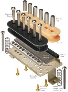
humbucker-internals1

Vintage Gibson Humbuckers Specs:
1956 – 1957 (“PAF”): Long (2.5”) Alnico 2, 3, 4 and 5 magnets used randomly, brushed stainless steel cover, *no* PAF sticker, automatic traverse wound with manual-stop (until bobbin was “full”), #42 plain enamel wire (purple/maroon), individual coil ohm differences, black leads on coils, ohms vary from low 7k to high 9k, black PAF-style bobbins (“square in circle” with holes). PAFs first installed on Gibson lap-steels in ‘56 and then guitars in ‘57.

1957 – 1961 (“PAF”): Long Alnico 2, 3, 4 and 5 used randomly (A2 most common), nickel cover, “Patent Applied For” sticker, automatic traverse-wound with manual-stop, #42 plain enamel wire (purple/maroon), individual coil ohm differences, black leads on both coils, ohms vary greatly – generally between 7k and 10k, black and cream (early-’59 thru mid-‘60), all bobbins black again by late ’60, PAF-style pickup bobbins.

1961 – 1962 (Late “PAF”): Smaller (2.37”) Alnico 5 magnet used for remaining production (all transitioned by July ’61), nickel cover, PAF sticker, automatic traverse-wound with manual-stop, #42 plain enamel wire (purple/maroon), black leads on both coils, individual coil ohm differences, ohms averaged 8.0k by ‘62, PAF-style bobbins.

1962 – 1964 (“Patent number”): Alnico 5, nickel cover, “patent no.” sticker (mid-’62), polyurethane wire (starting ‘63), black/white lead wires, “auto-stop” winding starts circa-’62, PAF-style bobbins, usually 7.6k – 8.0k ohm.

1965 – 1967 (Late “Patent number”): Alnico 5, polyurethane wire, “patent no.” sticker, bobbin wires white, Chrome cover (starts mid-’65), more durable and flatter bobbins with no “square in circle” hole circa-‘65, ohms usually between 7.4k – 8.0k. Gold-plated PAFs used in arch-top electrics as late as 1965 – “Varitone” guitars had gold-plated pickups with one pickup having a reversed magnet. This pickup style was used far less than nickel-plated pickups, thus inventory lasted thru 1965.

1967 – 1980 (“T-top”): “T” on bobbin top, Chrome cover, Alnico 5, polyurethane wire, automated winding begins ‘65 – ‘68, some ’69 – ’73 pickup covers embossed “Gibson”, “patent no.” sticker on baseplate ’67 – ’74, (patent number metal-stamped beginning 1974), ink stamp with date ’77 – ’80, ohms average 7.5k – consistently reading between 7.3k – 8.0k.

General Pickup Tech:

Alnico Magnet Types and Gauss
Magnetic flux is measured in Gauss – this is an indication of how strong a magnet is capable of being. Magnetic field intensity is measured in Oersteds. Technically speaking, the strength of a magnet is best measured as an approximate combined product of the Gauss and Oersteds. This is somewhat analogous to how electrical power in Watts is the product of Volts and Amps (Volts x mA = Watts). For example, 40 mA at 250 volts (40 x .250) produces 10 watts per tube, and the same 40 mA at 500 volts (40 x .500) produces 20 watts. So, when considering magnetic strength, ultimately, both Gauss and Oersteds are factors. That said, I’ll keep the scope of this article to the commonly used measurement of Gauss, as such understanding provides sufficient insight into magnetic properties relating to guitar pickups.

Alnico stands for Aluminum (Al), Nickel (Ni) and Cobalt (Co). Other than Iron (which comprises about 50% of all Alnico magnets), these are the main metals used in Alnico magnets.  All grades except Alnico IV have a bit of Copper (Cu) in them too. Alnico III contains no Cobalt. Alnico IV possesses the weakest gauss of all commonly used Alnico magnets, and Alnico V has the strongest gauss. More specifically, the order of Alnico magnet gauss level from weakest to strongest is:  Alnico IV -> Alnico III -> Alnico II -> Alnico V.  This said, though rare, one can still have an Alnico V magnet that’s weaker than an Alnico II, III or or even IV magnet, because magnets are not always fully charged.  Yet, Alnico V has the capacity to hold a stronger magnetic charge than Alnico II, III or IV.

Alloy

Al %

Ni %

Co %

Cu %

Gauss

Alnico II

10

19

13

3

7500

Alnico III

12

25

3

7000

Alnico IV

12

28

5

5600

Alnico V

8

14

24

3

12800

Following is data regarding gauss meter readings on approx 80 Alnico magnets. The magnet types checked were both polished and rough cast:

Various new Alnico II pickup magnets measured at gauss levels ranging from 22 to a high of 35, with most in the 25 to 30 gauss range.  New Alnico V magnets ranged from 22 to a high of 36, with most in the 30 to 35 gauss range.  Alnico V magnets tested from older Gibson “T-top” pickups (30+ years old) all measured in the 25 to 30 gauss range, with most reading 25 to 27 gauss. So, interestingly, older “T-top” pickups show moderate gauss level readings for Alnico V.  Vintage (late ’50s thru early ’70s) Gibson pickup magnet gauss readings, on both Alnico II and V magnets, consistently averaged 25 to 30 gauss.  And, all the magnets read stronger towards one end of the magnet, which could possibly have tonal implication on magnet orientation in the pickup.

The type and strength of magnet in a pickup can have about as much impact on tone as winding resistance. All other factors being equal, a weaker magnet effects tone by lowering both output and resonant peak (perceived as a less prominent high-midrange and treble response). While, contrarily, a stronger magnet will function to increase output and raise the resonant peak.  For example, a midrange-prominent humbucker reading in the higher ranges (say 9k+) might exhibit an output approaching that of a strong single-coil pickup, if it features a relatively weak magnet. And, conversely, a bright and airy sounding humbucker pickup reading in the lower ranges (say around 7.5k) can produce output akin to a typical “hotter” wound pickup, as is sometimes experienced with Alnico V magnet pickups like the”T-top”, for instance.

Additionally, long magnets (PAF-style) are slightly punchier sounding and have better tonal definition than shorter magnets – short magnets can sometimes produce a slightly “smeared” sound. Though magnet type can compensate for this, as Alnico V’s additional output, punch and brightness balanced out the shorter magnet size Gibson used beginning 1961.  Lastly, its worth mentioning how the stud-side pickup coil actually has slightly more output than the adjustable side on a traditional humbucker. There is a direct connection to the magnet inside the pickup on the stud side, while the adjustable pole extends out the bottom of the pickup. And, there is a slight loss of magnetic field and energy out the bottom of the pickup.

Bobbins, Wire and Winding
A pickup’s treble response is related to the magnet strength interacting with the windings. Think of it as a bell curve. The more winds, the brighter the pickup gets, but only up to a certain point. After that point more winds take away treble. The stronger the magnet the more winds you can add before the treble starts to drop off. Yet, all other factors being equal, inductance increases and treble response decreases, the higher the number of winds.

Resistance is only one indication of a pickup’s overall output – it tells a lot about the actual tonal character of a pickup only when considering the magnet that is used with it. And, bobbin types are key – skinny and tall coils produce a clearer sound than short and wide coils, all other factors being equal. Also, you can have a pickup with a higher resistance that has less output if the wire gauge is thicker or magnet gauss is lower than the pickup being compared. Or, you can have one pickup that is lower resistance with higher output if the wire is smaller diameter. Additionally, with tight wound coils the wire stretches a bit, which will give a higher resistance reading, because of the additional wire length. Loose winding generates a brighter tone, because with two identically sized coils wound from the same wire, the looser coil will have fewer winds than the tight coil.

Resistance is actually measuring the length of wire used in a coil and doesn’t necessarily indicate how many turns are used, as wire thickness and bobbin sizes vary. If a pickup is longer or larger, it will have the same resistance with less output due to the lower turn count. Turn count is really what determines output, but seeing how there is no way to count turns on an already wound pickup people use resistance for output comparison.

Fewer winds will have an audible effect, because the pickup will have less inductance, which affects the frequency response – making the pickup brighter. The pickup inductance interacts with the guitar volume/tone controls, guitar cable capacitance, and amplifier input load to create an EQ network. More inductance causes more highs to be lost in this EQ circuit. This also means that resistance ‘specs’ are misleading, because the turns count is what really makes the pickup sound they way it does. Inductance itself is related to the square of the turn count, so a small error in turns becomes a large error in inductance. By winding to a resistance value, you can’t get the turns count right because you don’t know what tension other pickup makers are using. But, by winding to a specific turn count or inductance value, you stand a much better chance of winding a successful pickup.

A traditional PAF pickup uses 42 gauge plain enamel insulation wire. Then there are other types of insulation like polyurethane, which would mean the coil wire might have a different overall diameter, so not all 42 gauge wire is created equal. There are also lighter wires, such as 43 or 44 gauges. In general, thinner wire will create a more high-frequency loss than thicker wire, all other factors being equal. Interestingly, in this same coil, polyurethane and heavy-build wire usually wind to same resistance and have the same inductance, and plain enamel is noticeably higher in resistance and inductance.

If you wind two identical coils, same resistance, but one with heavy-build insulation, the heavy build insulation coil will be noticeably brighter. It’s because there’s more capacitance going on since the actual metal in the wire has more gap between wires because it’s filled with heavier insulation. So, if that’s true then theoretically a looser coil would have the same effect. Moreover, polyurethane wire facilitates a punchier tone, while plain-enamel has a more vintage tonal character.

So, if other wire factors differ, you’ll have different behaviors. For example, if the coating has a different dielectric constant or thickness, the overall parasitic capacitance will change together with inductance, which shifts the resonant peak consequently. With loose windings or wire of same AWG but thicker insulation, you’ll have a lower inductance and parasitic capacitance, so even if the number of windings stays the same, the resonant peak will be higher and the output lower.

Rating Pickups with DC Resistance
DC resistance is NOT a power rating, rather its the resistance of the wire in a pickup’s coil at zero hertz, something that only occurs when a guitar isn’t played. DC resistance specs are inadequate as sole power and tone indicators of an AC device like a pickup. Small fluctuating AC (not DC) voltages from pickups are what control outpout from an amp or plate currents of a tube. The large current flowing through the plate fluctuates with the same frequency as the small guitar pickup voltage, and the tones we love come through. An amplifier makes the small AC signal coming from your guitar pickups big enough to move a speaker cone.

If we do use DC resistance as a parameter for indicating tonal response, for one, we disregard the fact that this resistance rating is frequency dependant. Tonal output varies across the frequency spectrum. Additionally, the pure output rating of a pickup is more accurately indicated in millivolts. Millivolts could be a helpful parameter in indicating pickup output and tone if manufacturers agreed on a standard measuring method that provides such data measured at various frequencies over a wide frequency range.

Inductance is another important parameter to consider in the sonic evaluation of a pickup. Put in simplest terms, as a general rule the higher the inductance, the lower the treble response and the higher the output and midrange emphasis will be. For examples, a traditional Strat pickup has an inductance around 2.3 henry, while a Gibson PAF has an inductance around 4.4 henry, and some of the so-called “distortion” pickups have an inductance above 8.0 henry. With these comparisons, you get a basic idea of this quality.

So, several important factors can to be considered to more accurately speculate the tone and output of a pickup – tone and output depend mainly on the relation between magnetic strength, wiring resistance and the resulting inductance of a pickup. And, don’t forget the relation between the inductance of the pickup and the capacitance of guitar cables and effects. Guitar cable capacitance especially impacts frequency response and output.

Pickup Cover Effects
Pickup cover types are another important aspect of tonal influence. Contrary to popular conception, it’s not so much whether you use covered or uncovered pickups that makes the most tonal difference. Nor, does the type of plating on a given cover make any considerable difference. Rather, what is most crucial to a pickup’s tone is two things: the exact metal or alloy a pickup cover is made of and the cover base thickness.

Solid-brass covers are usually the worst in terms of transparency and loss of high-end. Solid nickel-silver is the most transparent cover alloy, and it retains highs best. Yet, covers that are too thick (even nickel-silver) can impact tone as negatively as brass covers even. Specific covers to avoid are brass, too thick nickel-silver and cheap alloys in general, as varying compositions of metal alloy effects tone differently.

So, a quality nickel-silver cover that isn’t too thick will not exhibit tonal degradation compared to an uncovered pickup. Any competent pickup maker will know if the covers on their humbuckers are quality nickel-silver of moderate thickness, so be sure to ask when purchasing aftermarket pickups.

Other Factors Influencing Pickup Tone
The electric guitar is still fundamentally an acoustic instrument. And, any given pickup responds very differently to each and every guitar model. The wood (or other materials) of a guitar absorbs some frequencies and resonates others. And, a pickup only picks up the frequencies and levels that a string is generating. So, for instance, if you have a guitar that absorbs frequencies most readily between 200 and 500 Hz, you will likely have thinner sounding treble strings, than if the guitar absorbed higher range frequencies. If your guitar resonated well between the previously mentioned frequencies, it would facilitate beefier treble string response. Additionally, guitars that are more resonant allow you to use a lower output, brighter pickup and still get the same volume.

Last but not least, it is every player’s unique articulation and musicality that ultimately impacts a listener’s perception of tone. As intangible as this aspect is, every players unique touch is a crucial factor influencing tonal perception. Not convinced? I ask you this then: How many have heard mediocre players playing through the finest “holy grail” gear, whether live or on the internet, only to be left unmoved by the tone. And, conversely, how many have listened to recordings of brilliant players playing through something like a $50 battery-powered Pignose amp (as used on Derek and the Dominos’ Layla album, for instance), only to be left amazed at the tone achieved? I’ve experienced this phenomenon countless times – it’s the magic alchemy tone and musicianship.

Guitar Speaker Cabs: Various Types and Tones

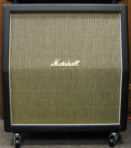
marshall-cab3

The following article addresses how different cabinet types impact guitar tone – the three most common cabinet types in particular:  closed-back, open-back and oval-back.  Not only do different speaker types and brands affect amplifier tone dramatically, the cabinet that your speakers are installed in shape that tone to practically the same degree. The following information explains the tonal characteristics of these different types of guitar amp speaker cabinets:

Closed-back Cabinets
A general rule of tone is simply that the bigger the box, the lower the frequency response of a closed-back cab. Yet, this is only true up to the point where a speaker can no longer produce lower frequencies. In a closed-back cabinet the sound waves produced from the back of the speaker simply bounce around inside the cabinet until they dissipate or “die.” And, as the back half of the speaker is in a partial vacuum, the speaker usually takes a little more power to get moving, so fast initial transient peaks can be a bit muted and be perceived as less loud than an open back cabinet – all other factors being equal. Additionally, closed-back cabinet designs can be darker toned than open-back cab designs.

Many old speaker cabinet designs used closed cabinets, and the frequency response was usually good, despite the fact that almost no design work was performed, as we see with Marshall cabinets and the like.  Closed-back cabinets are not very room or position dependent and can be used in most any live context.  With a closed-back cabinet design, bass response is increased, though high-end “airiness” is decreased. A closed back cab will have more bottom end thump.  It is also important to note that closed-back cabinets will sound dramatically different at various axis points (where the listener is located relative to the front of the cabinet). In general a closed back produces a more rock to hard rock tone.  An open-back cabinet is arguably best for blues into rock tone, producing a looser and more airy tone that fills a room all around more.

Open-back Cabinets
With open-back cabinets too, the bigger the box is, the lower the frequency response. And, especially with open back cabinets, the baffle-board that the speaker(s) is installed on impacts tone greatly too, so be aware of the baffle board that is utilized. Open-back cabinets mainly behave like dipoles – meaning sound is projected both forward and backward.  Additionally, a good strong tone is dependent on reflections from behind the cabinet too. This makes for that expansive, open and airy sound. However, this comes at the expense of bass response.  For, as sound is produced by both the front and the back of a speaker, open backed cabs can suffer phase cancellation problems as the sound produced by the back of the speaker is naturally 180 degrees out of phase with the sound produced by the front of the speaker. This can result in an unnatural sounding midrange and absent low mids/bass frequencies.

Of course the affects of this can be altered by room placement amongst other things. And, tone can differ a lot based on one’s position relative to the amp in the room. You have to good walls and surfaces for the rear-projecting tones to reflect off of to best use an open-back cab. Outdoors or in places where you have to jam the cab up against a wall just doesn’t work well. Additionally, both open and oval-back cabs will suffer the same fate pushed up against a wall. Open and oval-back cabinet designs (especially open-back) are very room and position dependent. Additionally, an open back cab will give you more volume, and the high end will be apparent further off axis.

Oval-back Cabinets
Those not very familiar with oval-back cabinets really need to look into this lessor known yet extremely effective cabinet design. As was all cabinets, the bigger the cabinet box is, the lower the frequency response of an oval-back system, as well. Factors like the baffle are key, as different thicknesses will all have different effects on tone. Same with the back opening – different resonances occur when you use different port sizes or openings, making various colorful sounds. Also, an oval back cab loads up the driver more and makes for a tighter sound with more bottom-end, yet with an opening back there, sound gets out and reflects off the back wall making for that more spacious sound.

The size of the oval port is were a lot of tone shaping comes into play.  With a smaller size hole, a cabinet will behave more like a ported cab than an open back cab. Various openings raise or lower the frequency where the rear waves become out of phase with the front and attenuate sound. The right size can add bottom-end extension and smooth out the lower midrange. Both a small oval opening acting like a port and various size oval openings facilitating less phase-cancellation at a lower frequencies, can create more bottom-end. So, various openings create more low-end – just in different ways based on the size.